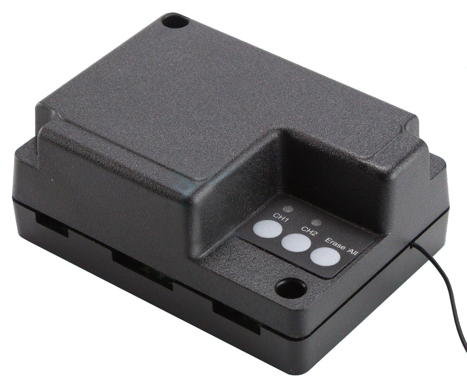
BOSS Receiver Coding
1. Connections
1.1 Connecting Power
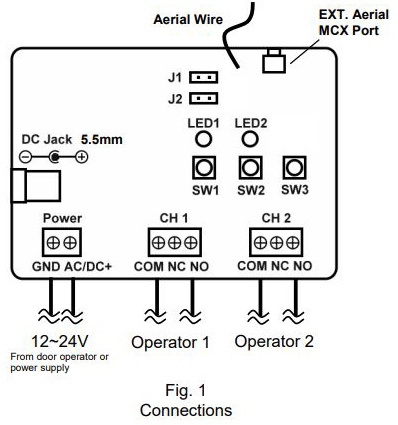
AC/DC 12-24V power can either be connected from door operator to the Power terminals, or DC12V power supply to the DC Jack.
Note: ONLY ONE power source can be applied.
NEVER connect power to both power inputs.
When power is connected, both LEDs will flash once.
1.2 Connecting Door Operator(s)
There are 2 channels (CH 1 & CH 2) for controlling up to 2 door operators. Each channel can be connected to function as Push Button for one door operator.
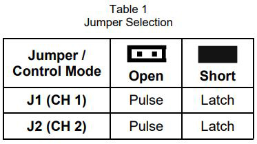
Use a pair of bell wires to connect “COM” and “NO” on one channel to Push Button terminals on a door operator. ( Refer to Table 1 for adjusting control mode if necessary.)
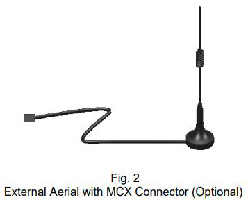 1.3 Connecting External Aerial (Optional)
When installing external aerial with MCX connector, cut the original aerial wire off the board to ensure receiving range and quality.
2. Programming Transmitters
2.1 Adding a Code
To program a transmitter, press and release the switch corresponding to the desired channel (e.g. SW1 for
Channel 1).
The LED (e.g. LED1 for Channel 1) will glow for 30 seconds. Press a button on transmitter or enter a PIN code on keypad. When the code is successfully programmed the LED will go off.
Upon activation from a programmed transmitter, the corresponding LED for the channel will flash twice.
Up to 20 codes can be programmed to a channel.
2.2 Erasing Codes
To erase ALL codes for a single channel, press and hold the corresponding switch (e.g. SW1 for Channel 1) for 5 seconds until the corresponding LED flashes 7 times.
To erase ALL codes for ALL channels, press and hold SW3 for 5 seconds until the both LEDs flash 7 times.
Please see coding guide here BOSS Receiver Coding